Whether it’s for a new vehicle line or part of a finite tool used in critical patient care, there’s no one way to design or produce the components comprising products used every day.
However, some production methods are more efficient and cost-effective than others.
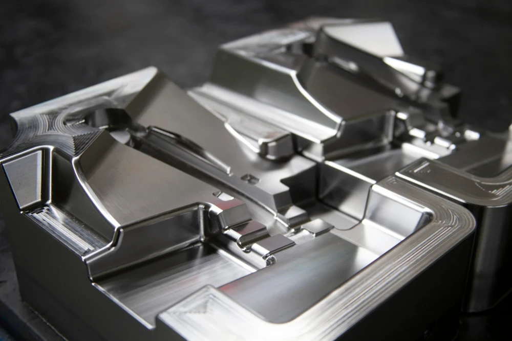
A common fabrication process, metal injection molding (MIM) checks both these boxes. It continues to improve and expand into new industries as an ever-growing process.
But like every other production process, MIM does require a high level of design factors to ensure finished products meet your exact specifications.
Metal Injection Molding: Overview & Advantages
From 1986 to 2004, the metal injection molding (MIM) market grew by almost 98% becoming a process worth $380 million. Today, the MIM market is worth $3.9 billion, an exponential growth with expectations to reach $7.1 billion by 2028.
From agriculture to the medical field, MIM has become an essential process in production. We’ll take a deeper dive into this later.
Why are so many industries producing with MIM?
Efficiency.
Metal injection molding is used for high-volume production, with low waste. It also boasts the ability to attain a part density of 94-97%, while still achieving industry-standard mechanical properties.
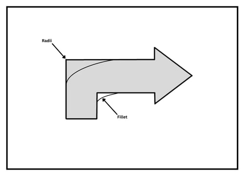
One technical advantage of MIM is its ease of integrating radii and fillets into product design. Both radii and fillets are curved surfaces, typically where two walls meet. Incorporating these design features provide engineers with design advantages, such as:
- Improved part strength
- Softening of sharp corners for handling/aesthetics
- Helps create a more robust tool, minimizing maintenance
8 Considerations for MIM Design
MIM is widely used, but when designing for MIM, there are eight factors to consider:
- Gate positioning
- Drag & sag effect
- Surface
- Draft angles
- Wall thickness
- Holes & slots
- Parting lines
- Witness marks
1. Gate Positioning
The gate is an opening in the mold, where the feedstock is injected – and the positioning can make or break your final product.
Locating gates to direct the flow onto a core pin or cavity wall is necessary, so the material flows from the thicker to thinner sections to ensure stability throughout the MIM process.
2. Drag & Sag Effect
The drag effect refers to the inherent shrinkage during the sintering process, shrinking part size by roughly 20%. Taking the drag effect into consideration ensures when the size is reduced, there are no surprises.
With the high temperatures during the sintering process (more on this later), parts become soft, creating a sag effect. If the sag effect isn’t considered during this stage, features won’t be supported and will sag due to gravity. Adding support structures to your design mitigates this.
3. Surface
The surface area is the flat surface along the outside of the part. When designing your MIM component, you’ll want a large, flat area or a common plane shared between the part’s features.
Doing this will eliminate the need for custom support structures and lessen the amount of framework needed to maintain the component’s structural integrity.
4. Draft Angles
During the MIM process, adding draft (tapering) to the faces of your component is crucial. Without it, the part will drag on the molded surface when it's being ejected, creating scratches on the surface finish.
To avoid damage to the component during part removal, the best practice is to add one degree of draft per one inch of cavity depth.
5. Wall Thickness
Maintaining a uniform wall thickness prevents sinks during the sintering process. If the wall isn’t thick enough, the features could break off.
6. Holes & Slots
Holes and slots add functional features to your component, provide uniform wall thickness, and reduce part mass. Even though they are very beneficial, adding such features does increase the complexity of the mold and thereby affecting your project’s budget.
7. Parting Lines
Parting lines appear when two halves of a mold come together. If you design with a flat area to set one of the halves on, it’s easier to use creative design to hide the parting line.
Pro Tip: Try to avoid setting pieces together that awkwardly overlap. This creates difficulties when setting the parts.
8. Witness Marks
MIM components often have witness marks, which are marks from parting lines, gates, and ejector pins. For some products, witness marks affect functionality or aesthetics negatively.
By keeping the location of the witness marks in mind in your design, you can control how visually apparent they are. Some designs have the marks depressed down so there’s nothing standing up on the surface.
MIM Design During Sintering
Sintering is the process of heating and applying pressure to material until it’s almost at its melting point. The last step in the metal injection molding process, ensures the physical and mechanical properties are optimal for fusing particles together.
Why is sintering so important in MIM?
As mentioned above, in the sintering phase drag effect shrinks your part by 20%! Taking shrinkage into consideration when sintering in MIM is critical so you aren’t surprised by the size difference. MIM excels at creating small, intricate parts typically ranging from .05g up to 100g. If you’re planning on designing a 100g part, a 20% size difference is huge.
Metal Injection Molding Applications
Discussing every application MIM is used for could go on for eternity. Instead, we’ll look at four industries in which MIM thrives – agriculture, automotive, firearms, and medical.
- Agriculture
- Automotive
- Firearms
- Medical
Agriculture
Strength and durability are necessary for heavy equipment like tractors to smaller tools in the agricultural field. Currently, MIM is widely used to produce tractor gears, bearings, and bushings, as well as devices from pruning shears to cultivators.
Automotive
In the automotive industry, MIM is widely used in countless parts. To put it in perspective, try driving a car with no seat components, brake parts, steering system, or any shift levers – you’d be better off walking without MIM in automotive production.
Firearms
MIM is used in the firearm industry mainly due to its ability to create precise, high-volume components – without losing quality. Hammers, triggers, and levers are just a few of the many gun parts made with metal injection molding.
Medical
In the fast-paced medical field, repeatability and precision are key factors. You’ll see MIM used in many medical devices from surgical instruments to orthopedic implants, like hip replacements, to even dental devices, such as implants and crowns.
The MIM Process: Investing in Quality
When designing, you need to keep MIM design criteria in mind, from start to finish. Metal injection molding can be an in-depth process, but the final component’s strength, durability, and precision will be worth the investment.
Ready to Design?
If you’re new to the MIM design process, it’s best to consult with an expert to understand when to use MIM and the complexities of the process.