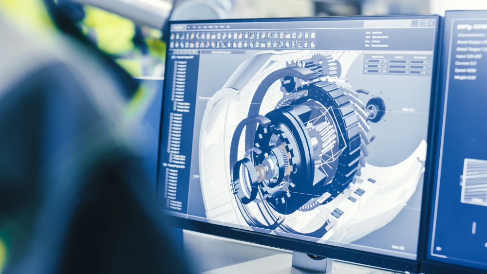
Design For Additive Manufacturing
Metal additive manufacturing has changed the way we think about design and production. It allows for the economical creation of lightweight parts with geometries that aren’t even possible with traditional manufacturing.
In order to take full advantage of metal AM, you should design 3D models by following the principles of the technology. Design for additive manufacturing (DFAM) involves integrating product design and additive manufacturing principles into a single activity.
How to Design for Additive Manufacturing - The Basics
Over the years, product design was driven by the intent of the designer and the final design was limited by the constraints of the manufacturing technology. When designing a part, you need to find an economical balance between functionality and quality. Traditionally, this was done by following design for manufacturing and assembly (DFMA), which focuses on reducing complexity to lower manufacturing costs.
While we were initially taught how to design parts for ease of manufacturing, with metal additive manufacturing, parts can be produced without geometry being a limiting factor. Metal AM has given engineers design freedom that could not be achieved using conventional manufacturing methods, due to manufacturing complications and high costs.
Additive Manufacturing Design Guidelines
When considering DFAM, there are several guidelines you should follow to ensure manufacturing costs are kept to a minimum, including:
- Part Consolidation
- Reduce Handling Time
- Modular Design & Multifunctional Parts
- Ease of Insertion
- Avoiding Common Manufacturing Defects
- Optimized Build Orientation & Minimal Support Structures
Part Consolidation
By consolidating a component into fewer parts, manufacturing time and assembly time can be reduced, along with costs. By reducing part count, fewer fasteners are required, fewer subcomponents need to be ordered and tracked, and there’s less chance for assembly error. Operation steps are also reduced, which lowers the number of operators, tools, and manufacturing equipment needed.
Reduce Handling Time
Loading components into a machine or processing parts are both examples of handling time. For example, a part may need to be loaded into machine A for one process, loaded into machine B, for a second, and machine C for a final process. This inevitably leads to wasted time and increased costs. If one machine could complete all three steps, handling times and overall costs could be reduced.
Modular Design & Multifunctional Parts
Additive manufacturing technologies allow for the design and manufacturing of nearly free-form geometry, which can be used to create more complex, multi-function or multi-feature parts. Using multifunctional parts is essential in reducing the number of sub-components. For example, a metallic structural part in one part may also be used as an electrical connector.
Ease of Insertion
To increase efficiency, it’s best practice to design parts that are easy to assemble. Designing features into parts such as guide rails can greatly speed up the assembly process. Additionally, designing components that can only fit together one way is also useful for reducing assembly time. An example of this concept is a UK electrical plug, which can only fit into the electrical outlet in one orientation.
Avoiding Common Manufacturing Defects
There are standard rules for each manufacturing technology that when followed, will reduce the likelihood of defective parts. For example, in metal injection molding, if the mold walls are too thin, the material may not completely fill, causing the component to fail. Just as with any other manufacturing process, during the DFAM stage, it’s best practice to re-evaluate your design to make sure it won’t cause manufacturing defects, or to modify designs to avoid features known to cause defects.
Optimized Build Orientation and Minimal Support Structures
Many 3D printed parts require support structures to avoid warping and drooping. These supports have to be later removed, which can be time-consuming and add to the component’s overall cost. You can minimize the need for supports through object orientation and by swapping out removable support structures with integrated elements and features.
Additive Manufacturing Design Software
Despite all the design freedom in metal AM, it can be time-consuming to create designs that fully capture its potential while minimizing its downsides. This has led to an increasing amount of additive manufacturing design software.
While they won’t replace your CAD program, these programs apply the benefits of additive manufacturing to your CAD file. They offer a variety of tools to help speed up the workflow of design, including:
- topology optimization
- lattice pattern generation
- generative design
- automatic lightweighting
- automated part consolidation
- stress, heat, and impact simulation
- build failure prediction
These tools are beneficial for designers and engineers who want to discover and experiment with new part forms, materials, and functions, in addition to those who want to put them to use as final parts.
Conclusion
Metal additive manufacturing allows for freedom of design, but you have to be cognizant of the characteristics and limitations of the technology, so you can design parts that can be manufactured successfully. Following best practices while designing for additive manufacturing can aid in making parts that are lighter, faster to build, and more cost-effective.
Check out our blog for more resources on additive manufacturing.
